project H:Prototype
DESIGN CHALLENGE
DYNAMIC SYSTEMS - responsive, adaptive, kinetic
The objective of this phase was to explore methods and techniques that we have mentioned in the previous phases in respect to the domain and the abstract of the research. As a kinetic exploration, control behaviour is explored. Global control triggers movement as a whole while local control triggers components within a system that can be controlled independently to each other.
FABRICATION AND ASSEMBLY
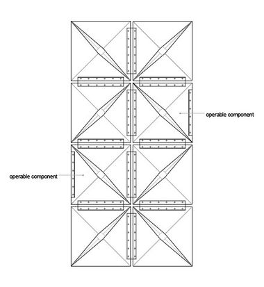
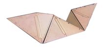
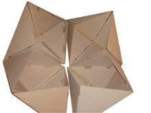
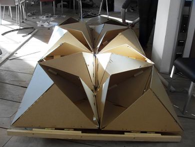
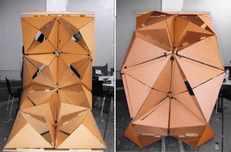
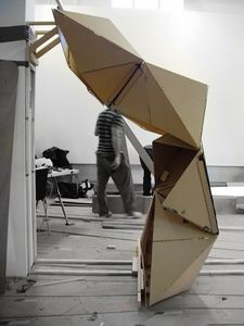
Based on the digital exploration, we realized that assembly process can be simplified by breaking the system down into repetitions of the same component. Eight elements made up a component. It is formed by eight components (four high, two wide) each component has a dimension of 70 X 70 cm. the size varies according to the opening of the component. Only two of the eight components are operable, this is due to the lack of actuators. To create an opening in one component two actuators are required, because the component opens on both sides. The other six components are fixed in an open position. Each component is made out of eight triangles of 3mm thick MDF.
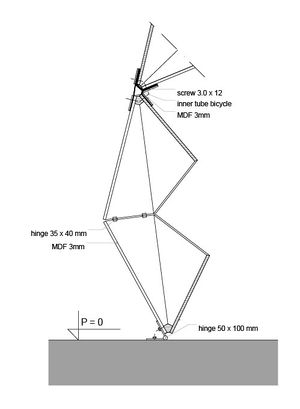
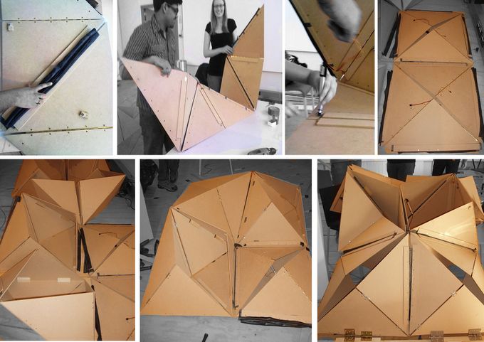
These triangular elements are planar and no special chamfer or bevel edges are needed. Parts fabrication is a simple and straight forward process while assembly is very labour intensive. Each element parts are connected to one and another by hinges and overall eight hinges, two inner tubes of a bicycle and about 72 screws were used for making a single component.
 In the assembly process of making 1:1 prototype, parts can be pre-assembled to step 5 for flat packaging using hinges in between. Parts from step 5 and step 6 are the only parts that need to be taken to the site for final assembly. With the 1:1 scale model, this arrangement create difficult to reach spaces and angles for the final assembly especially on verge of reaching step 7 where bike tire connections were required to be bolted. Constructing it on a desk/ studio is a challenge; however, constructing the final assembly on a real site is a different process that needs to be studied with further research.
The details first made for the prototype are altered. For external connections, an indigenous approach was formulated. Used rubber tubes from the bikes have been used for this purpose by creating layers for more strength and flexibility between the connections. The hinge from bicycle tires which also forms a connection between the component is changed. Instead of gluing the tires together and bolting it on the triangles. We cut the tires open and fix it with a wooden strip and screws on the triangles (see detail).
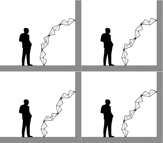
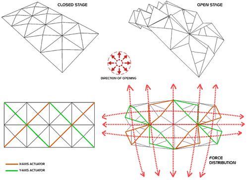
The final shape achieved is a arch like structure. In order to accomplish this shape, its components must be activated in sequence; either from the centre down to is edges or from the edges up to the centre. However, the most efficient way, is to actuate the components starting from the centre down to the edges.
Fabrication time:
4 hrs. (cutting panels)
14 hrs. (hinging elements together) (faster assembly process later due to gained experience)
Total fabrication time: 18 hrs.
Repairing the hinges + wood joinery: 8 hrs (Time consuming and major contributor to evaluation)
Subtotal: 26 hrs
Assembly line:
For number of elements, cluster and components
Actuators:
Depending on their performative need; these are capable to withstand forces under tension, compression, or a combination of both. Through out the fabrication from physical prototype, and the study of their kinetic behaviour, we are able to recognize the forces required in terms of structural integrity. In this case, we are aiming to introduce linear actuators not only for kinematic behaviour, but also as structural components. Therefore, for the purpose of these exercises, we will rely on actuators resisting both tension and compression forces. In turn maintaining continuous equilibrium within the system.
In respect to kinetic behaviour, every component in the system is equipped with two pairs of actuators. One pair running along the x-axis (horizontal displacement) and a second pair running along the y-axis (vertical displacement).
Both acting under tension and compression. Their application pushes the component apart for surface expansion and also pulls the component closer to itself for surface compression.
EVALUATION AND CONCLUSION
The component as such depends on the main structural performative system (origami), it is required for this unit to be adjustable and adaptable to its primary system. Therefore, several properties need to be adjusted such as; the overall geometry, movement range and mechanical complexity. Each of them has been evaluated deeply.
SYSTEM
As simple as this component is in its geometrical shape, and as easy it is to assemble, it only has one disadvantage. This disadvantage comes in terms of fabrication time. Due to the great number of elements that make up a single component which in turn must be multiplied in order to populate a surface, then, fabrication time becomes very consuming.
Once this pattern was assembled, one of the most important factors learned was the amount of force required to activate it. For instance, when the pattern was laying flat on the ground, it became almost impossible to fold up. Each element along the surface edges required an equal amount of force in order to engage it as a kinetic surface. Therefore, becoming even more difficult when being handled by only 3 people not being able to exert an even amount of force through out the surface.
System on just passing by the initial kinetic mode, there was a quantifiable decrease in the amount of force required for the surface pattern to keep on contracting. This displacement occurs along the z-axis and x-axis simultaneously. From this exercise, we can conclude that once the surface becomes kinetic, it must never come back to “0” curvature and it must remain at number greater than zero in order to minimize the amount of force required for actuation and to retain the overall shape of the structure.
MATERIALITY
For prototyping the use of MDF panels and brass hinges due to their performative value, doesn't seem to be the best solution. Materiality wise a better alternative material could be adopted. Both light and strong in nature, which can bear both tension and compression loads simultaneously.
CONNECTION
Different physical models and assembling processes made us realize the need to break down the system into components in order to design several configurations. At the same time we learned that different parameters will increase the adaptability factor within the system but at the same time increasing the complexity level of connections by multifarious extent.
Joinery done by using bike tire indigenous solution proved to be quiet effective and strong. That proved out to be a good solution. Joineries that were expected to perform didn't work out that well. For eg. Wood connections and hinge joineries.
AUTOMATION
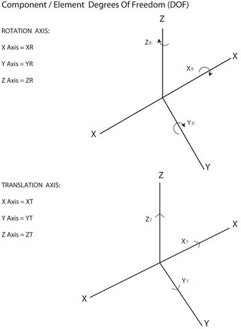
It corresponds to two elements hinged together allowing 4 degrees of freedom. One degree of rotation in the Y-axis, and another rotational degree of freedom in the X-axis, which as a result of coupling the two, we gain two new degrees of freedom as a translation movement in X and Y axis. We didn't take these two DOF into account and this is where we went wrong. However, to control patterns at a local level, we see the need to work with actuator types capable of resisting tensile and compressive forces. Force transfer turned out to be very complex and we somewhere we failed to take it completely in to account due to possible variations in component geometry which directly changed the forced vector in concurrent directions .
Actuators must be well calibrated and of right specification. Other alternate mechanisms could even be explored.
STRUCTURE
The structure exerts a greater force as they are engaged into a kinetic mode. This means that the stress distribution along the entire structure becomes greater, the torque between components increases, and when it comes to shape change, these forces become apparent as each component begins to twist and rotate influencing the final shape change. By observing this shape change, we are able to conclude that depending on the starting point of the sequence between local components, there is a domino effect that begins to elevate one component higher from the next as stress increases. However, this action allowed us to understand the distribution of stress, not only along the entire structure but also per component. Since the difference of forces between these components is much greater than in the previous configuration; their interaction can be mapped as a structural behaviour study and could be used to calibrate each component in greater detail.
From the prototyping explorations, we are able to conclude that we are partly able to create an interaction between the digital model and physical prototypes, we can conclude that we were able to make the transition between the computer model to the fabrication of the system. However, we must note that prior to the assembly process, small modifications must be taken into account due to the lack of material thickness within the digital model and due to the fact that hardware joins such as, brass hinges are not considered into the digital model. However, we are not able to simulate gravity, nor material weight. Therefore, encountering discrepancies between the digital model and physical prototypes. In respect to anchor points, we built every component without a foundation fixture. Therefore, allowing all components to freely interact with one another. The lack of anchor points however, allows us to address stress distribution along each configuration and at the same time makes it hard to maintain stability.
As estimated the costs incurred for the overall manufacturing went to around 90 Euros, i.e. each component costed around 10 Euros. That was an economical approach towards the prototype design considering the material and fixture costs.
We would like to end this project by summarizing and concluding our learning for further research development.

