project I:Realisation Plan
Contents |
Timeline of Realization
Technical implementation
The Shape
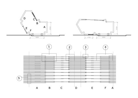
On the left you see the section of the structure and it shows you the shape of the whole object. As told the left part of the structure can be stretched and therefore the whole space can get bigger and smaller. Each Section is made out of several layers to have this possibility to chance the shape of the structure. This moving structure result in different joints for the corners of the whole shape. As shown in the details 1 to 5, these will be explained later on. To change the shape you need a force, because of the weight of the whole structure the blocks are mechanically adjustable, this is done by hydraulic pumps. As well as the corners the hydraulic pumps need a connection with the structure as well.
The Structure
In the image at the bottom you see an unfolded drawing of the structure. It shows how the sections are connected in the horizontal way. The shape exists out of 6 parts, these parts exists out of 1, 2 or 3 layers. In the middle you see the left side of the structure made out of two layers, these two layers are on both sides connected to the hydraulic pumps and these exist out of one layer. The hydraulic pumps are connected with the 2 layers triangle shaped frames, which forms a transition to the fixed part on the right side. The fixed part is made out of 3 layers to give it more stability. To construct the model you just need to connect the holes in the frames with each other. You only need to make sure that they are in the right order and the rest will follow.
Joints
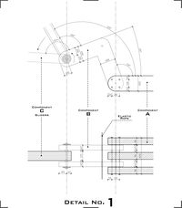
Detail 1
Drawn is the connection between the actuator and the triangle shaped transition. This triangle is fixed at the corner of the triple-layer part and flexible at the actuator side.
Step 1. : Take one layer of the big frame of the right site of the structure.
Step 2. : Take a bar and put this in the middle hole of the left-highest voids.
Step 3. : Place the triangle shaped element over the bar with the middle hole on the right side.
Step 4. : Screw this element on to the big frame, so that it is fixed. Put another big frame on top and fix this as well.
Step 5. : On the left side of the triangle there is another void. This void needs a big bar for the actuator. Put the hole of the actuator on top of the bar and close it with another triangle shaped element, which you fix on the other side on top of the second big frame.
Step 6. : Put an elastic robe through the hole in the corner of the triangle to connect the shape with the other sections.
Step 7. : Finish the joint with the last big frame and make sure that the two triangles are fixed in between.
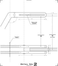
Detail 2
After you finished detail 1, you already have the actuator on the right side of detail 2.
Step 8. : Place the left-side frame on both sides of the actuator and connect them with the same bar as Step 5. But this time there is a bigger void to make possible that the actuator can slide, both the upper and the bottom of the big frame should be closed with some panels to avoid changing the direction of the actuator.
Step 9. : Use the same elastic robe as in Step 6 to connect the big frame with the other sections through the hole on the left side.
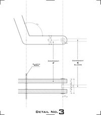
Detail 3
Detail 3 shows you how to connect the second actuator to the structure. On the left side the elastic robe again.
Step 10. : Connect the second actuator in between the two big frames, with a bar. This bar is fixed on one place, and the actuator should get bigger and smaller but staying in the same position compared with the other parts.
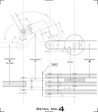
Detail 4
Here is where the hard work starts, so keep attention.
Step 11. : Place the actuator of Detail 3, in between two triangle shaped elements. At this point the actuator is flexible again, so placed on a round bar.
Step 12. : You’ve already made the three layers (Detail 1) you need on the right side of this detail. Place a wheel in between the first two layers en fix it with a bar. The wheel will stay turning because it is only kept on its place by the bar but not fixed onto the bar. This wheel makes sure that the whole construction can be moved. Another wheel should be attached on the right side of the bottom of the big frame.
Step 13. : Finish the whole structure by connecting the three big frames with the two triangle-shaped elements. But a bar through all the holes which are left over on the right side of the triangle and on the left side of the big frame.
Detail 5
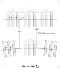
The whole shape is now made, the only thing left is to connect it with the rest of the frames (made in the same way). All the elastic robes you placed should form the connection between all the sections.
Final Step. : Place all the sections next to each other and connect them with the elastic robe. In between the sections should be placed a distance keeper, which makes sure the sections will keep their position.
Validation of realisation plan
Plan of Relationships
Other Atoms
Almost every Atom is providing a space for people to use. Some of them have the same idea of flexible spaces. During the second phase it was clear that every Atom had a different view on how to realize this flexible/usable space.
Other Projects
According to our design there is one project which is using something interesting, which could make our project complete.
Project C;
They use an interface to program the structure, this kind of programming the structure before you arrive could help us preparing the structure for events etc..
The so called 'Spacebook' is therefore an interface we are interested in to use in real life in combination with our structure.

