project K:Prototype
From student
(Difference between revisions)
(→TECHNICAL IMPLEMENTATION) |
|||
| Line 81: | Line 81: | ||
<gallery widths="190" heights="190" perrow="4"> | <gallery widths="190" heights="190" perrow="4"> | ||
File:Tech1.jpg|Structure system | File:Tech1.jpg|Structure system | ||
| − | File: | + | File:Tech2.jpg|Example |
| − | File: | + | File:Tech3.jpg|Example |
| − | File: | + | File:Tech4.jpg|Example |
</gallery> | </gallery> | ||
| Line 89: | Line 89: | ||
<gallery widths="190" heights="190" perrow=""> | <gallery widths="190" heights="190" perrow=""> | ||
| − | File: | + | File:Tech5.jpg|Path system |
| − | File: | + | File:Tech6.jpg|Detail |
| − | File: | + | File:Tech7.jpg|Detail |
| − | File: | + | File:Tech8.jpg|Detail |
</gallery> | </gallery> | ||
Revision as of 19:16, 1 February 2012
Contents |
PROTOTYPE DESIGN
CONCEPT

Movable system
The structure is adaptable, which allows the creation of different kinds of spaces and configurations. In this way the structure is able to adapt to environmental and social conditions. For example, forming a barrier if there is strong wind, or forming a shelter if it is raining. The structure will react specifically to local activities and conditions.
DESIGN


MODEL
General model

Structure functioning


Prototype 1:10 December 2011


Prototype 1:10 January 2012


Prototype 1:1 January 2012


TECHNICAL IMPLEMENTATION
Structure
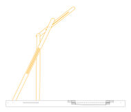
Structure system
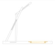
Example
Example
- Tech4.jpg
Example


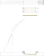
Path system
- Tech5.jpg
Path system
- Tech6.jpg
Detail
- Tech7.jpg
Detail
- Tech8.jpg
Detail


3D MODELS
