project K:Prototype
(→PROTOTYPE CONCLUSION) |
|||
| (33 intermediate revisions by 3 users not shown) | |||
| Line 11: | Line 11: | ||
'''Movable system''' | '''Movable system''' | ||
| − | The structure is | + | The structure is adaptable, which allows the creation of different kinds of spaces and configurations. In this way the structure is able to adapt to environmental and social conditions. For example, forming a barrier if there is strong wind, or forming a shelter if it is raining. The structure will react specifically to local activities and conditions. |
| + | <br> <br> <br> <br> <br> <br> | ||
| − | + | [[File: Systemfuncyion.jpg|960px]] | |
| − | ==<span style="color:orange"> | + | |
| + | ==<span style="color:orange">DESIGN</span>== | ||
| + | |||
| + | [[File: Cet1.jpg|315px]] [[File: Cet2.jpg|315px]] [[File: Cet3.jpg|315px]] | ||
==<span style="color:orange">MODEL</span>== | ==<span style="color:orange">MODEL</span>== | ||
| + | ===<span style="color:orange">General model</span>=== | ||
| − | [[File: | + | [[File: Seconda.jpg | frameless | 960px]] |
| − | ==<span style="color:orange"> | + | ===<span style="color:orange">Structure functioning</span>=== |
| − | == | + | <gallery widths="145" heights="150" perrow="5"> |
| + | File:Prot11.jpg| | ||
| + | File:Prot12.jpg| | ||
| + | File:Prot13.jpg| | ||
| + | File:Prot14.jpg| | ||
| + | File:Prot15.jpg| | ||
| + | </gallery> | ||
| − | <gallery widths=" | + | ===<span style="color:orange">Prototype 1:10 December 2011</span>=== |
| − | File: | + | |
| − | File: | + | <gallery widths="145" heights="150" perrow="5"> |
| − | File: | + | File:Prot21.jpg| |
| − | File: | + | File:Prot22.jpg| |
| + | File:Prot23.jpg| | ||
| + | File:Prot24.jpg| | ||
| + | File:Prot25.jpg| | ||
</gallery> | </gallery> | ||
| − | ===<span style="color:orange"> | + | |
| + | ===<span style="color:orange">Prototype 1:10 January 2012</span>=== | ||
| + | |||
| + | <gallery widths="145" heights="150" perrow="5"> | ||
| + | File:Prot31.jpg| | ||
| + | File:Prot32.jpg| | ||
| + | File:Prot33.jpg| | ||
| + | File:Prot34.jpg| | ||
| + | File:Prot35.jpg| | ||
| + | </gallery> | ||
| + | |||
| + | <gallery widths="145" heights="150" perrow="5"> | ||
| + | File:Prot41.jpg| | ||
| + | File:Prot42.jpg| | ||
| + | File:Proto43.jpg| | ||
| + | File:Proto44.jpg| | ||
| + | File:Proto45.jpg| | ||
| + | </gallery> | ||
| + | |||
| + | ===<span style="color:orange">Prototype 1:1 January 2012</span>=== | ||
| + | |||
| + | <gallery widths="145" heights="150" perrow="5"> | ||
| + | File:Prot51.jpg| | ||
| + | File:Prot52.jpg| | ||
| + | File:Prot53.jpg| | ||
| + | File:Prot54.jpg| | ||
| + | File:Prot51.jpg| | ||
| + | </gallery> | ||
| + | |||
| + | ==<span style="color:orange">TECHNICAL IMPLEMENTATION</span>== | ||
| + | |||
| + | ===<span style="color:orange">Structure</span>=== | ||
<gallery widths="190" heights="190" perrow="4"> | <gallery widths="190" heights="190" perrow="4"> | ||
| − | File: | + | File:Tech11.jpg|Structure system |
| − | File: | + | File:Deta1.jpg|Prototype |
| − | File: | + | File:Deta2.jpg|Prototype |
| − | File: | + | File:Deta3.jpg|Prototype |
</gallery> | </gallery> | ||
===<span style="color:orange">Path system</span>=== | ===<span style="color:orange">Path system</span>=== | ||
| + | |||
| + | <gallery widths="190" heights="190" perrow=""> | ||
| + | File:Tech21.jpg|Path system | ||
| + | File:Tech3.jpg|Detail | ||
| + | File:Deta4.jpg|Detail | ||
| + | File:Deta6.jpg|Detail | ||
| + | </gallery> | ||
<gallery widths="190" heights="190" perrow="4"> | <gallery widths="190" heights="190" perrow="4"> | ||
| − | File: | + | File:Path1.jpg| |
| − | File: | + | File:Path2.jpg| |
| − | File: | + | File:Path3.jpg| |
| − | File: | + | File:Path4.jpg| |
</gallery> | </gallery> | ||
| + | ==<span style="color:orange">3D MODELS</span>== | ||
| + | [[File: Ml1.jpg|960px]] | ||
| + | |||
| + | [[File: Lubrend.jpg|960px]] | ||
| + | |||
| + | =<span style="color:orange">PROTOTYPE CONCLUSION</span>= | ||
[[project K: experiments | '''Experiments and studies''']] | [[project K: experiments | '''Experiments and studies''']] | ||
| + | |||
| + | Moving from a large scale such as 1:10 to life-size prototypes is an unfathomably complicated jump. Seemingly benign decisions like connections types, material tolerances and assembly method attempt to derail the realization of the project as designed. This is not, however, without its purpose. In working at smaller scales it is easy to assume the prototype will assemble itself, and that these crucial decisions will be be made correctly the first time. Almost always this is not the case. Components must be disassembled, cut, reassembled, adjusted, checked, disassembled again, flipped over, mirrored, reassembled, repositioned, connected and the result is an “acceptable” representation of the original design. | ||
| + | |||
| + | In thinking what was learned through this prototype, I must say that have a coherent assembly system in mind beforehand would have saved massive losses of time and temper. Having an ikea-esque assembly diagram would have rendered the design basically correct on the first assembly. Alas, this was not on hand, and was indeed never conceived of, and the lack of assembly diagram caused the majority of problems with the prototype. | ||
| + | |||
| + | The success of the prototype is that through it I believed we have proven that our system can work, and through having one component that can shift position, we can achieve our languid, serpentine structure with ‘relative’ ease. | ||
| + | |||
</div> <div style="float: left; width: 900px; "> | </div> <div style="float: left; width: 900px; "> | ||
[[Project K:Home| Back to Home]] | [[Project K:Home| Back to Home]] | ||
</div> | </div> | ||
Latest revision as of 11:50, 2 February 2012
Contents |
PROTOTYPE DESIGN
CONCEPT

Movable system
The structure is adaptable, which allows the creation of different kinds of spaces and configurations. In this way the structure is able to adapt to environmental and social conditions. For example, forming a barrier if there is strong wind, or forming a shelter if it is raining. The structure will react specifically to local activities and conditions.

DESIGN


MODEL
General model

Structure functioning


Prototype 1:10 December 2011


Prototype 1:10 January 2012


Prototype 1:1 January 2012


TECHNICAL IMPLEMENTATION
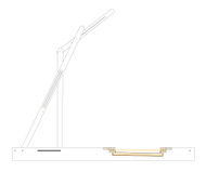
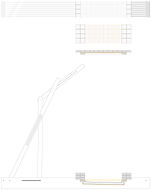
Structure
Structure system
Prototype
Prototype
Prototype


Path system
Path system
Detail
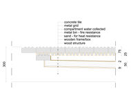
Detail
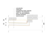
Detail


3D MODELS


PROTOTYPE CONCLUSION
Moving from a large scale such as 1:10 to life-size prototypes is an unfathomably complicated jump. Seemingly benign decisions like connections types, material tolerances and assembly method attempt to derail the realization of the project as designed. This is not, however, without its purpose. In working at smaller scales it is easy to assume the prototype will assemble itself, and that these crucial decisions will be be made correctly the first time. Almost always this is not the case. Components must be disassembled, cut, reassembled, adjusted, checked, disassembled again, flipped over, mirrored, reassembled, repositioned, connected and the result is an “acceptable” representation of the original design.
In thinking what was learned through this prototype, I must say that have a coherent assembly system in mind beforehand would have saved massive losses of time and temper. Having an ikea-esque assembly diagram would have rendered the design basically correct on the first assembly. Alas, this was not on hand, and was indeed never conceived of, and the lack of assembly diagram caused the majority of problems with the prototype.
The success of the prototype is that through it I believed we have proven that our system can work, and through having one component that can shift position, we can achieve our languid, serpentine structure with ‘relative’ ease.