project C:STRUCTURE
(→Component fabrication drawings) |
(→STRUCTURE DESIGN) |
||
| (62 intermediate revisions by 3 users not shown) | |||
| Line 15: | Line 15: | ||
'''- achieving over-pressure in the bottom components creates negative curvature and stiffens the whole structure - the counter-arch''' | '''- achieving over-pressure in the bottom components creates negative curvature and stiffens the whole structure - the counter-arch''' | ||
| − | |||
| − | |||
[[File:c_1.png|380px| generic component - the brick]] | [[File:c_1.png|380px| generic component - the brick]] | ||
[[File:c_2.png|380px| over-pressure - positive curve]] | [[File:c_2.png|380px| over-pressure - positive curve]] | ||
| + | |||
| + | <br> | ||
| + | <youtube width="370" height="250" right >4StyhrvVaEo</youtube> | ||
| + | The over-pressure in the inflatable tube has the effect of transforming the component into a curved beam-like element. | ||
The components have been weaved in a brick-like pattern for increased rigidity. The brick pattern is adopted for the top and bottom layers and for lateral component strips. | The components have been weaved in a brick-like pattern for increased rigidity. The brick pattern is adopted for the top and bottom layers and for lateral component strips. | ||
[[File:c_3.png|380px| elevation scheme with connections]] | [[File:c_3.png|380px| elevation scheme with connections]] | ||
| + | |||
[[File:c_4.png|380px| top view scheme]] | [[File:c_4.png|380px| top view scheme]] | ||
| Line 85: | Line 88: | ||
===<span style="color:orange">VALIDATORS</span>=== | ===<span style="color:orange">VALIDATORS</span>=== | ||
| − | [[Project C:structures_michela_turrin| Michela Turrin]] | + | [[Project C:structures_michela_turrin| Michela Turrin]], PhD researcher at Design Informatics:<br> |
| − | + | ''an elastic system of inflatables that form the structure is a possible system'' | |
| − | [[Project C:structures_gerrie_hobbelman | Gerrie Hobbelman]] | + | <br> <br> |
| + | [[Project C:structures_gerrie_hobbelman | Gerrie Hobbelman]], structural engineer:<br> | ||
| + | ''the linear system of arches is a viable structural system'' | ||
</div> | </div> | ||
| Line 96: | Line 101: | ||
====Cable pulley ground support system - concept==== | ====Cable pulley ground support system - concept==== | ||
| − | The strips are connected to the ground via cables attached to the pulleys. The pulleys are buried into the ground and the cables glide through small slits in the ground surface. The system holds the arch structure by tension of the cables activated by the pulley motors. Every arch patch has 4 cable anchors 2 for each support. | + | The strips are connected to the ground via cables attached to the pulleys. The pulleys are buried into the ground and the cables glide through small slits in the ground surface. The system holds the arch structure by tension of the cables activated by the pulley motors. Every arch patch has 4 cable anchors 2 for each support / arch ends. |
<gallery widths="210" heights="150" perrow="3" > | <gallery widths="210" heights="150" perrow="3" > | ||
| Line 103: | Line 108: | ||
File:pulley_3.png | multiple arches and cable - ground supports | File:pulley_3.png | multiple arches and cable - ground supports | ||
</gallery> | </gallery> | ||
| − | |||
====Movie==== | ====Movie==== | ||
| + | <youtube width="380" height="250" right >awMrVLLNx2g</youtube> | ||
| + | <youtube width="380" height="250" right >pyNmuzpYYAU</youtube> | ||
| − | + | ====Component fabrication drawings==== | |
| − | + | Each strip has a width of 3 m and comprises width-wise 12 components. | |
| − | <gallery widths=" | + | <gallery widths="345" heights="220" perrow="2" > |
File:crosssection-final.jpg|Cross section | File:crosssection-final.jpg|Cross section | ||
File:lengthsection-final.jpg|Length section | File:lengthsection-final.jpg|Length section | ||
| − | File:topview- | + | File:topview-final4.jpg|Cross section |
| − | File: | + | File:Elevation1-5-final.jpg|Elevation |
</gallery> | </gallery> | ||
| + | [[File:scale-final.jpg|780px|linear component 1st test model - ground supports and connections not designed]] | ||
| − | + | ====Prototype pictures==== | |
| − | + | ||
| − | [[File: | + | <div style="float: left; width: 380px; margin-right:10px; text-align:justify"> |
| − | + | [[File:scale_system1.jpeg|380px]] | |
| − | - | + | Scale surface system |
| − | + | </div> | |
| − | - | + | <div style="float: left; width: 380px; margin-right:10px; text-align:justify"> |
| − | + | [[File:scale_system2.jpeg|380px]] | |
| − | - | + | Scale surface system |
| − | + | </div> | |
| − | - | + | <div style="float: left; width: 380px; margin-right:10px; text-align:justify"> |
| − | + | [[File:scale_surface.jpeg|380px]] | |
| − | + | Scale surface | |
| + | </div> | ||
| + | <div style="float: left; width: 380px; margin-right:10px; text-align:justify"> | ||
| + | [[File:scale_detail.jpeg|380px]] | ||
| + | Scale surface system detail | ||
| + | </div> | ||
</div> | </div> | ||
</div> | </div> | ||
| + | |||
<div style="float: left; width: 1200px; margin-right:40px; text-align:left"> | <div style="float: left; width: 1200px; margin-right:40px; text-align:left"> | ||
[[Project C:Home|go back to project page >>]] | [[Project C:Home|go back to project page >>]] | ||
</div> | </div> | ||
Latest revision as of 19:25, 8 December 2011
STRUCTURE
CONCEPT
In order to make a fully adaptable construction, the structural system should provide for both positive and negative curvatures. A system of inflatable components is implemented and will work in this manner:
- achieving over-pressure in the top components creates positive curvature in the structure - the arch
- achieving over-pressure in the bottom components creates negative curvature and stiffens the whole structure - the counter-arch


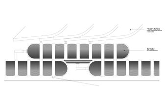
The over-pressure in the inflatable tube has the effect of transforming the component into a curved beam-like element.
The components have been weaved in a brick-like pattern for increased rigidity. The brick pattern is adopted for the top and bottom layers and for lateral component strips.


Air-valve diagram system - every patch / strip has 2 compressors for each layer; every component has one on-off valve

RESEARCH
Over the duration of the course several structural systems have been analyzed:
- muscle / pulley system
- cube- grid system
- hanging system
- inflatable system
The result of the analysis is that the inflatable system seemed to offer the best performance regarding the concept implemented. Two options for the inflatable system were discussed:
Linear component

Bubble component

After analyzing both options the general conclusion is that the linear component presents a better performance regarding the project concept and final implementation. The main reasons for choosing the linear component are:
- the linear component presents similar structural stiffness as the bubble component
- the linear component has better dynamics with the component frame
- the linear component is better suited for fluent, flowing arches that are inline with the concept
- the linear component has a simpler tube and valve infrastructure
- the linear component has better material implementation regarding the 1:1 scale prototype
References
VALIDATORS
Michela Turrin, PhD researcher at Design Informatics:
an elastic system of inflatables that form the structure is a possible system
Gerrie Hobbelman, structural engineer:
the linear system of arches is a viable structural system
STRUCTURE DESIGN
Cable pulley ground support system - concept
The strips are connected to the ground via cables attached to the pulleys. The pulleys are buried into the ground and the cables glide through small slits in the ground surface. The system holds the arch structure by tension of the cables activated by the pulley motors. Every arch patch has 4 cable anchors 2 for each support / arch ends.
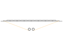
the arch is in default position - the pulley wires are not in tension
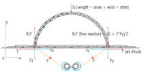
the components inflate - the arch rises - the pulley wires are tensioned and support the structure
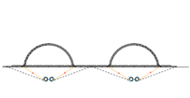
multiple arches and cable - ground supports


Movie
Component fabrication drawings
Each strip has a width of 3 m and comprises width-wise 12 components.
Cross section
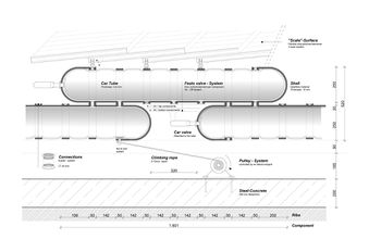
Length section
Cross section
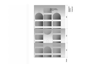
Elevation


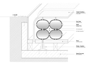
Prototype pictures
 Scale surface system
 Scale surface system
 Scale surface
 Scale surface system detail