project B:Realisation Plan
(→Use after completion) |
|||
| (118 intermediate revisions by 2 users not shown) | |||
| Line 1: | Line 1: | ||
| − | <div style="position: absolute; top: 40px; left: 570px; width: 250px; height: 470px | + | <div style="position: absolute; top: 40px; left: 570px; width: 250px; height: 470px;" > |
| − | + | ||
| − | == | + | </div> |
| + | |||
| + | <div style="position: absolute; top: 0px; left: 30px; width: 820px; height: 150px;" > | ||
| + | <div style="position: absolute; top: 10px; left: 0px; width: 790px; height: 150px;" > | ||
| + | |||
| + | HyperPublic : '''[[Project B:Home|Home]]''' / '''Realisation Plan''' | ||
| + | ---- | ||
| + | |||
| + | After making various sketches and lasercut models at 1:10 scale, we decided the best way to actually convince others of the quality of the design, would be to start think about the full-scale model early on in the process. We created many prototypes at full scale to learn more about the milling process and material properties in respect to our design. When we were confident that the prototypes of parts of the connections were all functioning well, we decided to create two full-scale models to be able to show different configurations at the same time and to be able to explain te relation between the two elements and show their differences. | ||
| + | |||
| + | |||
| + | Below, you find a movie of the end result of this process, in which we built up the model in protoSPACE 3.0 at BK City (Faculty of Architecture) of the TU Delft. | ||
| + | |||
| + | |||
| + | <youtube width="790" height="400" right>PH34-ddAIeA</youtube> | ||
| − | |||
| − | |||
| − | |||
| − | |||
| − | + | ==Facts== | |
| + | [[File:IMG 4615 cropped.jpg|150px|thumb|right|Extended the QR code to save weight]] | ||
| + | The total milling time in machine hours needed for the full-scale prototypes are approximately 16 hours with a 10mm drillbit at 60% speed. | ||
| − | + | 7 Plates of 2440x1220x18mm MDF and 6 steel hinges were the only materials required. | |
| − | + | The total maeterial costs were about € 220,-. | |
| − | + | The two prototypes consist out of 87 MDF parts, of which 32 are completely unique. | |
| − | + | The weight of the heaviest piece is approximately 12 KG after CNC milling and can easily be lifted by one person. | |
| + | <div style="position: absolute; top: 1020px; left: 0px; width: 395px; height: 255px;" > | ||
| + | <youtube width="395" height="250" right>IZiKJ1DVMLk</youtube> | ||
</div> | </div> | ||
| + | <div style="position: absolute; top: 1020px; left: 395px; width: 395px; height: 255px;" > | ||
| + | <youtube width="395" height="250" right>CYjSKhNXqdE</youtube> | ||
</div> | </div> | ||
| − | |||
| − | |||
| − | |||
| − | |||
| − | |||
| − | |||
| − | |||
| − | |||
| − | |||
| − | |||
| − | |||
| − | |||
| − | |||
| − | |||
| − | |||
| − | |||
| − | |||
| + | ==Lessons learned== | ||
| + | [[File:Hinges.JPG|150px|thumb|right|Hinges]] | ||
| + | [[File:Stability.JPG|150px|thumb|right|Stability]] | ||
| + | [[File:Milling problems.JPG|150px|thumb|right|Milling problems]] | ||
| + | [[File:Tolerances.JPG|150px|thumb|right|Tolerance]] | ||
| + | [[File:Milling_drillhead.JPG|150px|thumb|right|Milling drillhead]] | ||
| + | '''Hinges''' | ||
| + | Because of a change by the manufacturer of the hinges we bought at a hardwareshop, (which were mirrored compared to our protoped version). Next time we should buy them all at once and check for this. | ||
| + | |||
| + | '''Stability''' | ||
| + | Because some of the seating/stairs boards were not completely stable, we decided to create extra stabilising triangular supports. | ||
| + | While we were milling, we also found out that it’s very hard to mill on both sides of a MDF plate accurately. So the lower ends of our basic elements are at this moment not yet connected. | ||
| Line 89: | Line 99: | ||
| + | |||
| + | '''Milling problems''' | ||
| + | Because we drew some of the elements with the startpoint of the polylines at corners, some of the parts came loose before they were completely cut out. We adjusted this by creating new startpoints at the long edges of the drawings. | ||
| + | |||
| Line 96: | Line 110: | ||
| + | '''Tolerances''' | ||
| + | Since some detailed extensions, such as the armrests needed to be created very precisely, we had to make several models in which we tried out tolerance differences of .5 mm to see if the stability would increase. On most of the parts this had the desired effect, so we can still take it apart easily without any tools. | ||
| + | |||
| Line 102: | Line 119: | ||
| + | '''Milling drillhead''' | ||
| + | We had a problem with the drillhead which seemed not be able to follow the inside of the curves which had the same radius as the drillhead,After testing, we found a way to create a better toolpath which resulted in the desired effect. | ||
| Line 110: | Line 129: | ||
| + | '''Material strength''' | ||
| + | While standing or sitting on the [http://x.vu/236193 lowest element] it bends a little, so people will feel it's not safe. That's why in the future extra supports should be added. | ||
| + | '''Material properties''' | ||
| + | The MDF sawdust seemed to be very toxic, which is why we used masks to filter our inhaled air. This worked pretty well, but our eyes still got irritated. | ||
| + | |||
| + | |||
| + | '''Setting up RhinoCAM files''' | ||
| + | |||
| + | We felt it took a long time to set up the milling files in Rhino with RhinoCAM. We downloaded the program so we could work on it from home before coming to protoFAB, but there were problems when using our files in protoFAB. It would be great if there were a separate computer with the program installed outside of protoFAB which would save a lot of fabrication time. | ||
| + | |||
| + | |||
| + | |||
| + | |||
| + | |||
| + | |||
| + | ==No screw no glue== | ||
| + | |||
| + | |||
| + | [[File:Facit-factory.jpg.644x0 q100 crop-smart.jpg|250px|thumb|right|[http://www.3ders.org/articles/20120116-digitally-fabricated-houses-of-facit-homes.html on site fabrication]]] | ||
| + | |||
| + | We decided to go for the "No Screw No Glue" design method. Not because of it's sustainable character, but because we tried to create an easy to use and changeable design. | ||
| + | |||
| + | By creating a design for which you would need only three things (CNC milling machine, standard sized 18mm MDF plates and hinges) we feel that this adds to fast on site construction, which is shown in a real life example with a CNC milling machine in a container in the picture. | ||
| + | |||
| + | This had major implications in our design, since every part of the structure should be able to come apart to it's basic components. At places where you'd normally would screw to fix a piece, we have designed specific solutions to counter the imbalance and tolerances which are inherent in a design process such as ours. | ||
| + | |||
| + | |||
| + | In the movie below, you can see an example of one of the extensions which is being taken apart piece by piece in just 30 seconds. | ||
| + | |||
| + | |||
| + | <youtube width="790" height="400" right>ypPRpsfbSDM</youtube> | ||
| + | |||
| + | |||
| + | |||
| + | |||
| + | ==Use after completion== | ||
| + | |||
| + | Below you can find a series of pictures of people already using the prototypes , sometimes in ways we did not intend, which is great. | ||
| + | |||
| + | <gallery perrow="4" caption=""> | ||
| + | File:UseFinalModel1.JPG | Coatrack | ||
| + | File:UseFinalModel2.JPG | Desk | ||
| + | File:UseFinalModel3.JPG | Standing table | ||
| + | File:UseFinalModel4.JPG | More comfortable seating | ||
| + | </gallery> | ||
| + | |||
| + | |||
| + | |||
| + | |||
| + | |||
| + | |||
| + | |||
| + | |||
| + | |||
| + | |||
| + | |||
| + | |||
| + | |||
| + | |||
| + | |||
| + | |||
| + | |||
| + | |||
| + | |||
| + | |||
| + | |||
| + | |||
| + | |||
| + | |||
| + | |||
| + | |||
| + | |||
| + | |||
| + | |||
| + | |||
| + | |||
| + | |||
| + | |||
| + | |||
| + | |||
| + | |||
| + | |||
| + | |||
| + | |||
| + | |||
| + | </div> | ||
| + | </div> | ||
| Line 424: | Line 530: | ||
| − | HyperPublic : '''[[Project B:Home| | + | HyperPublic : '''[[Project B:Home|Home]]''' / '''Realisation Plan''' |
Latest revision as of 09:45, 4 February 2012
HyperPublic : Home / Realisation Plan
After making various sketches and lasercut models at 1:10 scale, we decided the best way to actually convince others of the quality of the design, would be to start think about the full-scale model early on in the process. We created many prototypes at full scale to learn more about the milling process and material properties in respect to our design. When we were confident that the prototypes of parts of the connections were all functioning well, we decided to create two full-scale models to be able to show different configurations at the same time and to be able to explain te relation between the two elements and show their differences.
Below, you find a movie of the end result of this process, in which we built up the model in protoSPACE 3.0 at BK City (Faculty of Architecture) of the TU Delft.
Contents |
Facts

The total milling time in machine hours needed for the full-scale prototypes are approximately 16 hours with a 10mm drillbit at 60% speed.
7 Plates of 2440x1220x18mm MDF and 6 steel hinges were the only materials required.
The total maeterial costs were about € 220,-.
The two prototypes consist out of 87 MDF parts, of which 32 are completely unique.
The weight of the heaviest piece is approximately 12 KG after CNC milling and can easily be lifted by one person.
Lessons learned


Hinges
Because of a change by the manufacturer of the hinges we bought at a hardwareshop, (which were mirrored compared to our protoped version). Next time we should buy them all at once and check for this.
Stability
Because some of the seating/stairs boards were not completely stable, we decided to create extra stabilising triangular supports.
While we were milling, we also found out that it’s very hard to mill on both sides of a MDF plate accurately. So the lower ends of our basic elements are at this moment not yet connected.
Milling problems
Because we drew some of the elements with the startpoint of the polylines at corners, some of the parts came loose before they were completely cut out. We adjusted this by creating new startpoints at the long edges of the drawings.
Tolerances
Since some detailed extensions, such as the armrests needed to be created very precisely, we had to make several models in which we tried out tolerance differences of .5 mm to see if the stability would increase. On most of the parts this had the desired effect, so we can still take it apart easily without any tools.
Milling drillhead
We had a problem with the drillhead which seemed not be able to follow the inside of the curves which had the same radius as the drillhead,After testing, we found a way to create a better toolpath which resulted in the desired effect.
Material strength While standing or sitting on the lowest element it bends a little, so people will feel it's not safe. That's why in the future extra supports should be added.
Material properties
The MDF sawdust seemed to be very toxic, which is why we used masks to filter our inhaled air. This worked pretty well, but our eyes still got irritated.
Setting up RhinoCAM files
We felt it took a long time to set up the milling files in Rhino with RhinoCAM. We downloaded the program so we could work on it from home before coming to protoFAB, but there were problems when using our files in protoFAB. It would be great if there were a separate computer with the program installed outside of protoFAB which would save a lot of fabrication time.
No screw no glue

We decided to go for the "No Screw No Glue" design method. Not because of it's sustainable character, but because we tried to create an easy to use and changeable design.
By creating a design for which you would need only three things (CNC milling machine, standard sized 18mm MDF plates and hinges) we feel that this adds to fast on site construction, which is shown in a real life example with a CNC milling machine in a container in the picture.
This had major implications in our design, since every part of the structure should be able to come apart to it's basic components. At places where you'd normally would screw to fix a piece, we have designed specific solutions to counter the imbalance and tolerances which are inherent in a design process such as ours.
In the movie below, you can see an example of one of the extensions which is being taken apart piece by piece in just 30 seconds.
Use after completion
Below you can find a series of pictures of people already using the prototypes , sometimes in ways we did not intend, which is great.
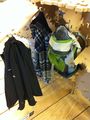
Coatrack
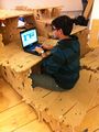
Desk
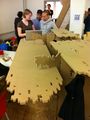
Standing table
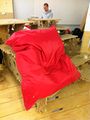
More comfortable seating


HyperPublic : Home / Realisation Plan