project B:Realisation Plan
(→Facts) |
|||
| Line 35: | Line 35: | ||
<youtube width="250" height="155" right>CYjSKhNXqdE</youtube> | <youtube width="250" height="155" right>CYjSKhNXqdE</youtube> | ||
</div> | </div> | ||
| + | |||
| + | |||
| + | |||
| + | |||
| + | |||
| + | |||
| + | |||
| + | |||
| + | |||
| + | |||
| + | |||
| + | |||
| + | |||
| + | |||
| + | |||
| + | |||
| + | |||
| + | |||
| + | |||
| + | |||
==Lessons learned== | ==Lessons learned== | ||
Revision as of 11:25, 2 February 2012
HyperPublic : Home / Realisation Plan
After making various sketches and lasercut models at 1:10 scale, we decided the best way to actually convince others of the quality of the design, would be to start think about the full-scale model early on in the process. We created many prototypes at full scale to learn more about the milling process and material properties in respect to our design. When we were confident that the prototypes of parts of the connections were all functioning well, we decided to create two full-scale models to be able to show different configurations at the same time and to be able to explain te relation between the two elements and show their differences.
Below, you find a movie of the end result of this process, in which we built up the model in protoSPACE 3.0 at BK City (Faculty of Architecture) of the TU Delft.
Contents |
Facts
The total milling time in machine hours needed for the full-scale prototypes are approximately 16 hours with a 10mm drillbit at 60% speed.
7 Plates of 2440x1220x18mm MDF and 6 steel hinges were the only materials required.
The total maeterial costs were about € 220,-.
The two prototypes consist out of 87 MDF parts, of which 32 are completely unique.
The weight of the heaviest piece is approximately 12 KG after CNC milling and can easily be lifted by one person.
Lessons learned
Hinges (pic)
Because of a change by the manufacturer of the hinges we bought at a hardwareshop, (which were mirrored compared to our protoped version). Next time we should buy them all at once and check for this.
Stability (pic driehoeken)
Because some of the seating/stairs boards were not completely stable, we decided to create extra stabilising triangular supports.
While we were milling, we also found out that it’s very hard to mill on both sides of a MDF plate accurately. So the lower ends of our basic elements are at this moment not yet connected.
Milling problems (pic)
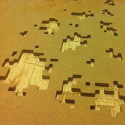
Because we drew some of the elements with the startpoint of the polylines at corners, some of the parts came loose before they were completely cut out. We adjusted this by creating new startpoints at the long edges of the drawings.
Tolerances (pic maatvoering armsteunen)
Since some detailed extensions, such as the armrests needed to be created very precisely, we had to make several models in which we tried out tolerance differences of .5 mm to see if the stability would increase. On most of the parts this had the desired effect, so we can still take it apart easily without any tools.
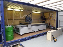
Milling drillhead (pic CNC freesmachine)
We had a problem with the drillhead which seemed not be able to follow the inside of the curves which had the same radius as the drillhead,After testing, we found a way to create a better toolpath which resulted in the desired effect.
aangeven dat we pas echt precies zijn gaan laseren toen we 1op1 hadden gemaakt, daarvoor alleen principes. Heeft voor en nadelen. Want detail niveau had in dit geval enigszins ook in laser gemaakt kunnen worden en dan hadden we misschien al die tabiliteitproblemen precies kunnen aan zien komen.
Erachter gekomen met organiseren samenwerking studenten dat bet niet zomaar gaat, je moet eerst iets aanbieden waarop voortgeborduurd kan worden. Daarom goed basistype ontworpen en zelf het goede voorbeeld te geven door als eerste gebruikers aanpassingen op dat systeem te maken.
We merkten dat studenten weinig konden leren van voorgaande projecten en na gesprekken met de docenten merkten we dat het idee leefde om een database te maken met bestaande projecten, maar dat daarvan af werd gezien doordat zon database snel okt of dat zou raken. Daarom gebruik gemaakt van zeer flexibel systeem dmv protoTAG waardoor onderdelen maar ook prototypes en model snel en simpel opgenomen kunnen worden in de database. Ook andere (studenten) kunnen hier gebruik van maken of aanvullingen op doen.
Door veel onderzoek en ontwerptool te steken in het maken van modellen 1op1 Model
No screw no glue
We decided to go for the "No Screw No Glue" design method. Not because of it's sustainable character, but because we tried to create an easy to use and changeable design. This had major implications in our design, since every part of the structure should be able to come apart to it's basic components. At places where you'd normally would screw to fix a piece, we have designed specific solutions to counter the imbalance and tolerances which are inherent in a design process such as wours.
In the movie below, you can see an example of one of the extensions which is being taken apart piece by piece in just 30 seconds.
Eenvoudig systeem, complexe configuraties, aanpassingen en extensies mogelijk
Door laagdrempelig te máken, ipv Het ontwerpen voor slimme ontwerpers die al met Rhino en Grasshopper kunnen omgaan hopen we meer mensen te vinden die er gebruik van zullen maken.
Referentie: Wikihouse, werkt ook met SketchUp en dat soort simpele programmas.
Aangehouden standaard CNC machine en verder kan in de toekomst een script gesxhreven worden dat alle verhoudingen en afmetingen binnen wiskunde regels over de dikte en verhoudingen van alle onderdelen.
Maak tekening met basisverhoudingen, tov van elkaar. Dus diepte gat is 2x xxx en hoogte trap dingen = 1/6 totale hoogte. Totale hoogte max 1200 en breedte max 2400 .. Etc
"Totaal: Zijn mensen er al enthousiast over? Willen ze ermee verder?
Tomasz --> moet ook biertje kunnen houden
Christian --> probeerde uit zichzelf al verschillende onderdelen te scannen
"
mogelijk nog toevoegen:
kapstok
wielen
REFERENTIE CNC FREES IN CONTAINER

dit hieronder kan volgens mij weg
\/\/\/\/\/\/\/\/\/\/\/\/\/\/\/\/
Development path
01 - testing fabrication methods
02 - presenting design ideas and incorporating feedback in design
03 - generate an overview of available materials and making design scalable
04 - testing tolerances and usability scale 1:10 with CNC milling machine (in absence of lasercutter)
05 - generating final 1:10 scale model to present to protoSPACE staff incuding Kas Oosterhuis weeks before final presentation
06 - using feedback to adjust and generate a part of the design scale 1:1 to face final challenges in connections, size and weight
07 - after a 'go' talk to large scale manufacturers in the area to help them sponsor machine time on large scale CNC milling machines
08 - gaining approval by presenting to protoSPACE staff to create the complete project scale 1:1 and showing final calculations
09 - build final design scale 1:1 with sponsoring of milling time by company and only material investment of Hyperbody
10 - taking surveys to compare to survey at the beginning of the semester to see if our goals are met
11 - structure all relevant generated texts, (computer)models and knowledge in a form future users could learn from or can adjust (parts of) the design
Fabrication
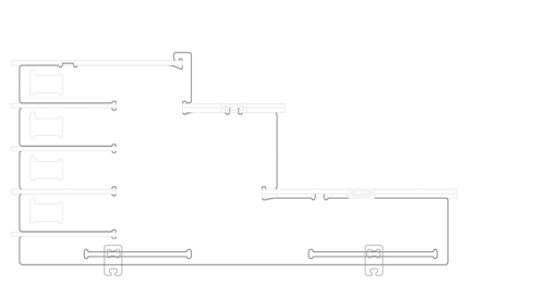
Below is a sequence of images which shows an example of what kind of challenges we face while actually fabricating our design. Therefor the fabricationprocess is an important element in shaping our structural elements.
In the complete design, we have thought about drillhead sizes, wood board thickness and dimensions, scalability and the limits of the CNC milling machine. By making samples of just the connections on 1:10 and 1:1 scale, we have already found out some fabrication tolerances and we will keep working this way between the design and fabrication to create an actual fabricated 1:1 model as an end goal for this MSc1 course.
HyperPublic : Home / Realisation Plan

