project C:REALIZATION PLAN
(→User case scenarios) |
(→REALIZATION PLAN) |
||
| (101 intermediate revisions by 4 users not shown) | |||
| Line 1: | Line 1: | ||
| + | __NOTOC__ | ||
| + | [[Project C:Home|go back to project page >>]] | ||
| + | |||
<div style="float: left; width: 1200px; margin-right:10px; text-align:left"> | <div style="float: left; width: 1200px; margin-right:10px; text-align:left"> | ||
=<span style="color:orange">REALIZATION PLAN</span>= | =<span style="color:orange">REALIZATION PLAN</span>= | ||
| − | <div style="float: left; width: 380px; margin-right:30px; text-align: | + | <div style="float: left; width: 380px; margin-right:30px; text-align:left"> |
| − | ===<span style="color:orange"> | + | ===<span style="color:orange">TECHNICAL IMPLEMENTATION</span>=== |
| − | + | The architectural fabrication consists of 4 major aspects: | |
| − | + | '''Inflatable Structures:''' | |
| − | + | - Application of bike tube materials to increase the strength of inflatables | |
| + | |||
| + | - Application of valve for better performance of maintain air pressure | ||
| − | - | + | - Application of outer skin for protection of inflatables |
| − | - | + | - Application of composite materials as inflatables frame |
| − | ''' | + | '''Air Pump System:''' |
| − | - | + | - Application of PVC tube for even distribution of air pressure |
| − | - | + | - Application of electrical pumping system |
| − | + | - Application of compressor for accurate air pressure supply | |
| − | + | '''Pulley System: ''' | |
| + | - Application of pulley for flexible changing of stings profile | ||
| − | + | - Application of pulley motor support the pulley system | |
| − | + | '''Control System: ''' | |
| − | + | - Application of computational control system as central control system to operate pulley and inflation/deflation system. | |
| − | + | ||
| − | + | - Application of remote control system instead of on site operation | |
| − | |||
| − | |||
| − | |||
| − | </ | + | ===<span style="color:orange">RELATION OF PROJECT</span>=== |
| − | + | '''Relation to other atom(s): ''' | |
| − | + | [[atom08:Home|Atom 8]] is creating a structure that can incorporate many different activities but changes its appearences due to parameters related to (eg) sunlight, noise and user density. This could become an extension of the Spacebook structure system. | |
| − | |||
| − | ''' | + | '''Relation to other project(s): ''' |
| − | + | [[project_E:Home|Interactive border]] is as a possible solution for Spacebook furniture | |
| + | [[project_G:Systems|Flexscape]] is a possible system for a user adaptable floor | ||
| − | |||
| − | [[File: | + | [[File:relations_projects.jpg |380px|left]] |
| − | |||
| − | |||
| − | |||
| − | |||
| − | |||
| − | |||
| − | |||
| − | |||
| − | |||
| − | |||
| − | |||
| − | + | '''Relation to other developments on the site: ''' | |
| − | + | - Some of the strips will serve as a (covered) walkway for connecting the BK city to the Science Centre and the Botanical Gardens. | |
| − | |||
| − | + | ===<span style="color:orange">FINANCIAL REALIZATION</span>=== | |
| − | + | ||
| − | + | There are several financial plans that could finance (or contribute to financing) Spacebook. | |
| + | |||
| + | 1. Advertisement on Spacebook website. | ||
| + | |||
| + | 2. Advertisement on site -> Promotional furniture or product testing. | ||
| + | |||
| + | 3. Renting the site to companies for promotional events. | ||
| + | |||
| + | 4. Make Spacebook the showpiece of TU Delft and/or the Municipality of Delft -> use their promotional budget. | ||
| − | |||
===<span style="color:orange">VALIDATORS</span>=== | ===<span style="color:orange">VALIDATORS</span>=== | ||
| − | + | '''Future users''' showed in their [[atom02:Questionnaire_results|questionnaire results]] there is a demand for Spacebook. | |
| − | + | '''Johan Bogaart''', graduate student in Architectural Engineering:<br> | |
| + | ''"Spacebook is bringing people together in the next age. It is innovative and has a rich potential."'' | ||
| − | + | '''Jurjen de Jong''', student Civil Engineering:<br> | |
| + | ''"I like the idea of Spacebook. When you are also able to create some privacy, I see potential in the project."'' | ||
| − | + | '''Emil Heeren''', graduate student in Aerospace Engingeering:<br> | |
| + | ''"It is like the future of on-line community:"'' | ||
| − | + | '''Cecilia Chui''', MSC4 student in Architecture (TUD):<br> | |
| + | ''"To having a transformable structure for different activities is so interesting.I think it would be much more powerful for your project to make some expression on the enclosed space."'' | ||
| + | '''Arthur Verkerke''', musician:<br> | ||
| + | ''"This is a great idea for making music or organizing parties."'' | ||
</div> | </div> | ||
<div style="float: left; width: 780px; margin-right:10px; text-align:justify"> | <div style="float: left; width: 780px; margin-right:10px; text-align:justify"> | ||
| − | ===<span style="color:orange"> | + | ===<span style="color:orange">MATERIAL LIST for FABRICATION</span>=== |
| + | <div style="float: left; width: 370px; margin-right:10px; text-align:left"> | ||
| + | ''Material list for 1 : 5 prototypes - phase II'' | ||
| + | [[File:1_5_list_2.jpg|365px|left]] | ||
| + | </div> | ||
| + | <div style="float: left; width: 380px; margin-right:10px; text-align:left"> | ||
| + | ''Material list for 1 : 1 prototypes - Phase III' | ||
| + | [[File:1_1_list_2.jpg |380px|right]] | ||
| + | </div> | ||
| − | + | <div style="float: left; width: 780px; margin-right:10px; text-align:justify"> | |
| − | + | ===<span style="color:orange">REALIZATION TIMELINE</span>=== | |
| − | + | ||
| − | [[File: | + | [[File:timeline.jpg |780px|left]] |
| + | </div> | ||
| − | |||
| − | = | + | <div style="float: left; width: 780px; margin-right:10px; text-align:justify"> |
| + | ===<span style="color:orange">1:1 MODEL PROPOSAL</span>=== | ||
| − | ''' | + | For the 1:1 model a small portion of the structure will be build: a fragment of the strip that is anchored to the ground. |
| + | |||
| + | '''- the inflatable units are connected to the ground with hinge elements which eliminate horizontal forces in the structure and at the same time provide the rotation freedom for the creation of the arch''' | ||
| + | |||
| + | '''- the pressure installation is located underneath the floor surface''' | ||
| + | |||
| + | '''- the air is sucked into the system via a grid in the pavement''' | ||
| + | |||
| + | '''- through the wall air tubes will lead to the inflatable units''' | ||
| + | |||
| + | |||
| + | <div style="float: left; width: 380px; margin-right:10px; text-align:justify"> | ||
| + | [[File:Atom2_001.jpg|380px]] | ||
| + | 1:1 model flat | ||
| + | </div> | ||
| + | <div style="float: left; width: 380px; margin-right:10px; text-align:justify"> | ||
| + | [[File:atom2_002.jpg|380px]] | ||
| + | 1:1 model in position (rotated) | ||
| + | </div> | ||
| + | |||
| + | </div> | ||
| + | </div> | ||
| + | |||
| + | |||
| + | <div style="float: left; width: 1200px; margin-right:10px; text-align:left"> | ||
| + | [[Project C:Home|go back to project page >>]] | ||
| + | |||
| + | [[Project C:PROTOTYPE|see the prototyping progress >>]] | ||
| + | </div> | ||
Latest revision as of 16:25, 12 December 2011
REALIZATION PLAN
TECHNICAL IMPLEMENTATION
The architectural fabrication consists of 4 major aspects:
Inflatable Structures:
- Application of bike tube materials to increase the strength of inflatables
- Application of valve for better performance of maintain air pressure
- Application of outer skin for protection of inflatables
- Application of composite materials as inflatables frame
Air Pump System:
- Application of PVC tube for even distribution of air pressure
- Application of electrical pumping system
- Application of compressor for accurate air pressure supply
Pulley System:
- Application of pulley for flexible changing of stings profile
- Application of pulley motor support the pulley system
Control System:
- Application of computational control system as central control system to operate pulley and inflation/deflation system.
- Application of remote control system instead of on site operation
RELATION OF PROJECT
Relation to other atom(s):
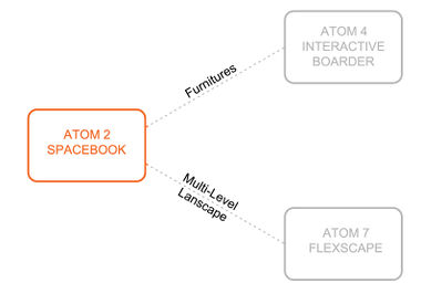
Atom 8 is creating a structure that can incorporate many different activities but changes its appearences due to parameters related to (eg) sunlight, noise and user density. This could become an extension of the Spacebook structure system.
Relation to other project(s):
Interactive border is as a possible solution for Spacebook furniture
Flexscape is a possible system for a user adaptable floor
Relation to other developments on the site:
- Some of the strips will serve as a (covered) walkway for connecting the BK city to the Science Centre and the Botanical Gardens.
FINANCIAL REALIZATION
There are several financial plans that could finance (or contribute to financing) Spacebook.
1. Advertisement on Spacebook website.
2. Advertisement on site -> Promotional furniture or product testing.
3. Renting the site to companies for promotional events.
4. Make Spacebook the showpiece of TU Delft and/or the Municipality of Delft -> use their promotional budget.
VALIDATORS
Future users showed in their questionnaire results there is a demand for Spacebook.
Johan Bogaart, graduate student in Architectural Engineering:
"Spacebook is bringing people together in the next age. It is innovative and has a rich potential."
Jurjen de Jong, student Civil Engineering:
"I like the idea of Spacebook. When you are also able to create some privacy, I see potential in the project."
Emil Heeren, graduate student in Aerospace Engingeering:
"It is like the future of on-line community:"
Cecilia Chui, MSC4 student in Architecture (TUD):
"To having a transformable structure for different activities is so interesting.I think it would be much more powerful for your project to make some expression on the enclosed space."
Arthur Verkerke, musician:
"This is a great idea for making music or organizing parties."
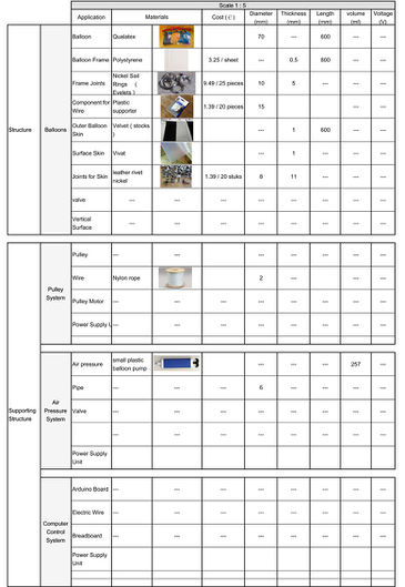
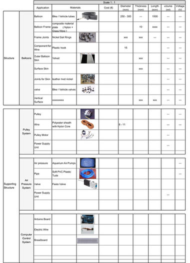
MATERIAL LIST for FABRICATION
1:1 MODEL PROPOSAL
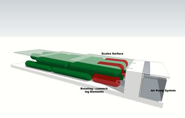
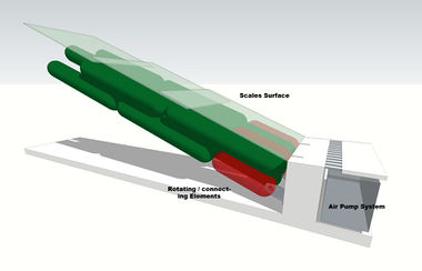
For the 1:1 model a small portion of the structure will be build: a fragment of the strip that is anchored to the ground.
- the inflatable units are connected to the ground with hinge elements which eliminate horizontal forces in the structure and at the same time provide the rotation freedom for the creation of the arch
- the pressure installation is located underneath the floor surface
- the air is sucked into the system via a grid in the pavement
- through the wall air tubes will lead to the inflatable units
