project I:Home
Contents |
- Concept: FLEXIBLE SPACE
Activate the Site-System by integrating it with the surroundings, and creating flexible space.
- The Whole Site
1.Layers of Structure
Three Layers of Structures

1. A Dynamic Structure - Comprised by kinetic structures;
2. Ground - Using light symbols or interactive technologies to control road and pedestrians;
3. Underground - Operable structures prepared underground for temporary use, such as facade and space division.
Kinetic Structure

By creating a road the space is divided into smaller spaces.
Video of the moving road model
The road is on top of the third layer, when it's moving it creates different spaces. The problem with these three layers is that the weight of the traffic is on top of all layers.
Two Layers

The models and diagrams showed us that the layers 'Ground' and 'Underground' as shown in the first image are actually one. So if we combine these layers we only create
1. A Structure
2. The Ground
The spaces on both side of the road are therefore constructed out of two or more objects.
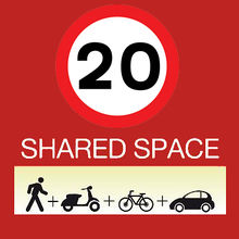
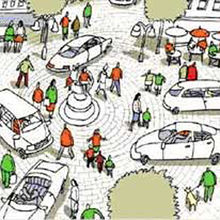
Shared Space: This concept is designed by Mr. Monderman, it is designed to create safety without rules. It should make people aware of eachother, 'Respect instead of rules'. Everybody can make use of this space if they keep their speed limit to 20 km/h.
In our design the 'Ground Layer' is a shared space.
Shared Space Entrance

The site has several entrances. These four entrances are connected to the surrounding traffic system.
Traffic Sign Location

To make clear which entrance the road users should take, the surrounding systems should be provide with signs to inform them. The orange circles show where the signs should be located to prevent confusing situations.
Road Directions 1

The road can be connected to the surrounding traffic systems in different ways, here you can see several of them.
Road Directions 2

- Two Solutions: Umbrella & The Beast
1. Umbrella


Structure
The edges of the umbrellas are connected and reacting on eachother. Each umbrella has sensors which are reacting on the sun/rain/wind/night/etc... Besides that they can be programmed for special days, for example events. The only disadvantage of the umbrella is that the space underneath the created roofs is 'flat', it has no accomodations.

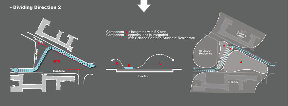
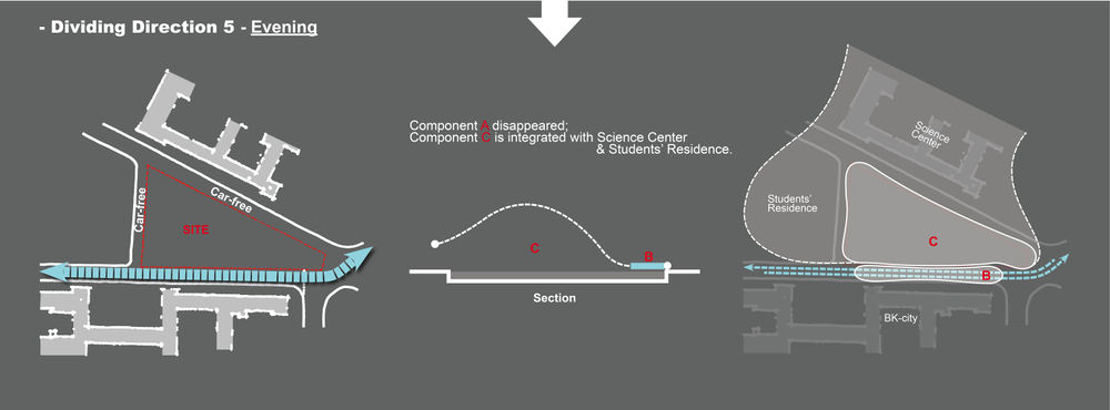
Situation 1: This image shows how the road divides the site into two spaces. Green used by BK-City, red used by Science Centre and the student residential.

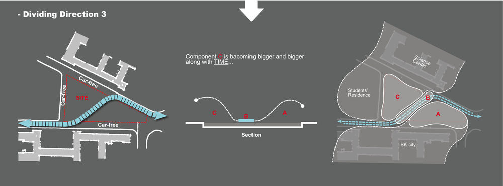
Situation 2: When the road changes its direction the spaces could be divided in different ways. The umbrellas are creating roofs and seperations between spaces.

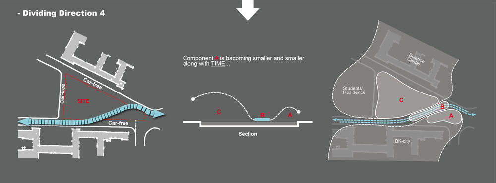
Situation 3: When the road is at its 'maximum' the site can be used for events or the Mondays when the Science Centre is closed.
2. The Beast

Space for Traffic Road

Open Space

Road Directions 1

Road Directions 2


Why Choose Solution 2
Solution 2 is a structure which creates spaces and facilities/accomodations in one. The structure itself is formed to create comfortable spaces.
- The Structure
1. Angles & Shape Research

Text Text Text Text Text Text Text Text Text Text Text Text Text Text Text Text Text

Text Text Text Text Text Text Text Text Text Text Text Text Text Text Text Text Text

Text Text Text Text Text Text Text Text Text Text Text Text Text Text Text Text Text

Text Text Text Text Text Text Text Text Text Text Text Text Text Text Text Text Text

Text Text Text Text Text Text Text Text Text Text Text Text Text Text Text Text Text

Text Text Text Text Text Text Text Text Text Text Text Text Text Text Text Text Text

Text Text Text Text Text Text Text Text Text Text Text Text Text Text Text Text Text

Text Text Text Text Text Text Text Text Text Text Text Text Text Text Text Text Text

Text Text Text Text Text Text Text Text Text Text Text Text Text Text Text Text Text
2. Two Modes

Animal Mode: Text Text Text Text Text Text Text Text Text Text Text Text Text Text Text Text Text

Worm Mode: Text Text Text Text Text Text Text Text Text Text Text Text Text Text Text Text Text
3. Flexiblilities

Rolling

Turning/Rotating

Folding

Differentiating/Smaller, Bigger
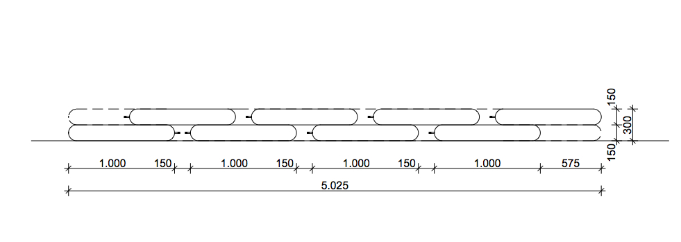
4. Sizing


5. Jointment Researches

Void & Ball

Three Layers & Bar

Gears

Streching
To create the structure we needed to figure out how the corners of the model will be connected with eachother. Because we have parts which are not fixed but movable, there where adjustable connections needed. On the left you see four options to connect two parts while they can still be manipulated, for example rotated or streched.
6. Supporting the Structure

Hydraulic
An Extra Bar outside
Streaming Water inside
Pulleys
Text Text Text Text Text Text Text Text Text Text Text Text Text Text Text Text Text Text Text Text Text Text Text Text Text Text Text Text Text Text Text Text Text Text Text Text Text Text Text Text Text Text Text Text Text Text Text Text Text Text Text Text Text Text Text Text Text Text Text Text Text Text Text Text Text Text Text Text Text
Manually Controlled
Machanical Controlled
Text Text Text Text Text Text Text Text Text Text Text Text Text Text Text Text Text Text Text Text Text Text Text Text Text Text Text Text Text Text Text Text Text Text Text Text Text Text Text Text Text Text Text Text Text Text Text Text Text Text Text Text Text Text Text Text Text Text Text Text Text Text Text Text Text Text Text Text Text
Previous References
For the further part of the project, there're several possible materials and technics: Steel, Wood, Inflatable Skin or Membrane, and etc.
1. Steel
Triangle Steel Rods
Accessible Roof

Waving Kinetic

Sliding Bars & Pulleys

2. Wood
Interactive for Users

Adjustable Nude

Flexible Space 1

Flexible Space 2

Flexible Space 3


