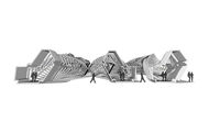
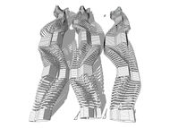
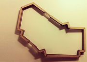
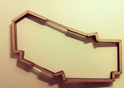
project I:The Structure
</div>
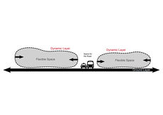
Two Layers:
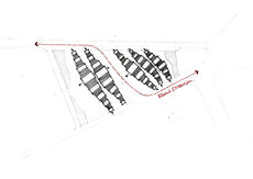
The models and diagrams showed us that the layers 'Ground' and 'Underground' as shown in the first image are actually one. So if we combine these layers we only create
1. A Structure 2. The Ground
The spaces on both side of the road are therefore constructed out of two or more objects.
About The Structure
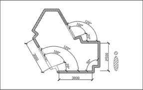
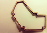
1. Angles & Shape Research
Different angles with different degrees used in architecture are for various of behaviors.
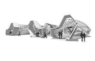
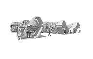
The space will differentiate through the changing of the degree, thus adapt to users behaviors.
2. Four Modes
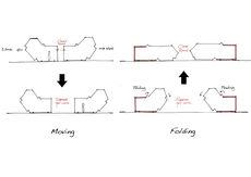
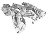
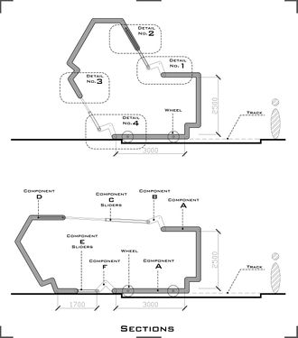
Rotating/Turning Mode: Some of the sections of the Beast are fixed. The space is differentiating by the changing of their width and height.
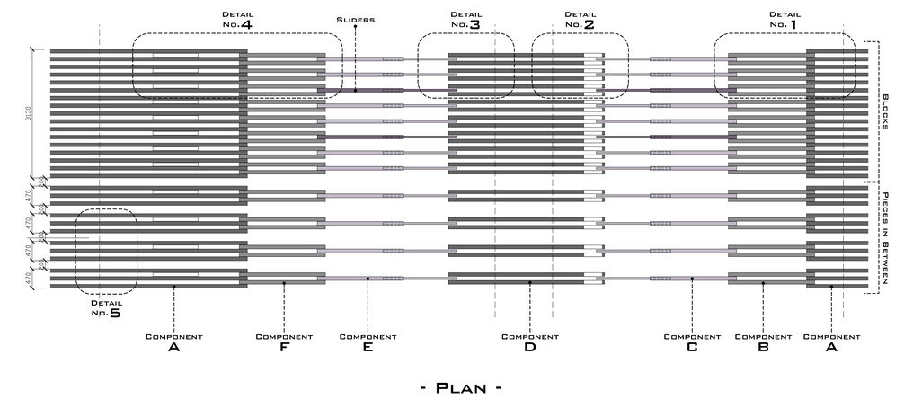
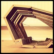
Folding/Stretching Mode: There are two components of each piece of The Beast is acting like a worm: stretching itself and folding to another shape. Part I is always fixed and part II is flexible.
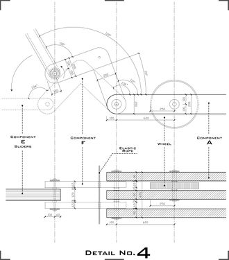
Rolling Mode: The Beast is sometimes performing like a snake, it moves by rolling it's wheels. The wheels are rolling in some designed tracks which guide the structure moving in a proper way.
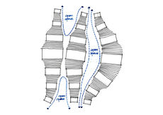
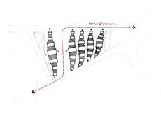
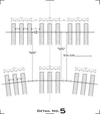
Sizing Mode: The size of the sections through the body of the Beast is growing and shrinking, by which the structure provides many possibilities for different size of space.
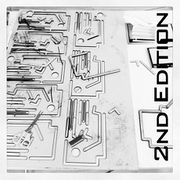
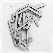
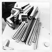
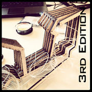
5. Process Models & Joints Experiments
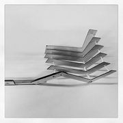
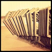
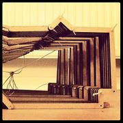
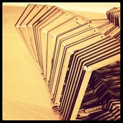
In the 1st few models we were focusing on how to realize the flexibility of the structure.
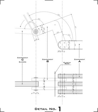
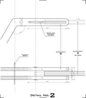
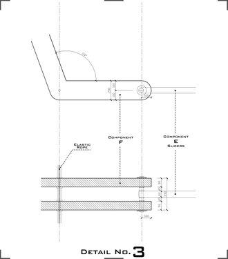
Since the structure needs to be flexible, and at the same time stable and controllable, thus some of the joints should be adjustable and some fixed. There are several kinds of joints: fixed joint, rotating joint, stretching joint and linking joint.
After several experiments on models, we found that the most difficult part was to make the structure stand up and stable.
Thus we tried a few solutions, such as parallelogram with springs, pulleys with strong ropes, etc. Finally we decide to use a simple sliders controlled by a hydraulic. It's a machanical way to manipulate the large and heavy part of the structure, and for the small parts (two ends of each row) would be easy controlled by users.

