project B:Realisation Plan
| Line 29: | Line 29: | ||
HyperPublic : '''[[Atom01:Home|Theory: Home]]''' / '''[[Project B:Home|Project B: Home]]''' | HyperPublic : '''[[Atom01:Home|Theory: Home]]''' / '''[[Project B:Home|Project B: Home]]''' | ||
---- | ---- | ||
| + | |||
| + | ==Development path== | ||
'''01 -''' testing fabrication methods | '''01 -''' testing fabrication methods | ||
| Line 51: | Line 53: | ||
'''11 -''' structure all relevant generated texts, (computer)models and knowledge in a form future users could learn from or can adjust (parts of) the design | '''11 -''' structure all relevant generated texts, (computer)models and knowledge in a form future users could learn from or can adjust (parts of) the design | ||
| + | |||
| + | <br> | ||
| + | |||
| + | ==Fabrication== | ||
| + | |||
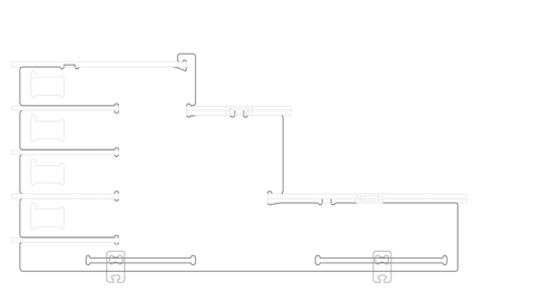
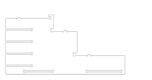
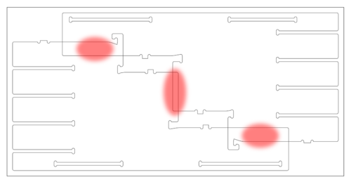
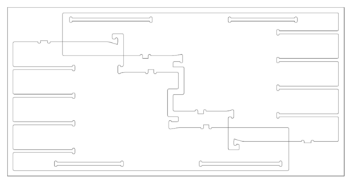
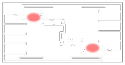
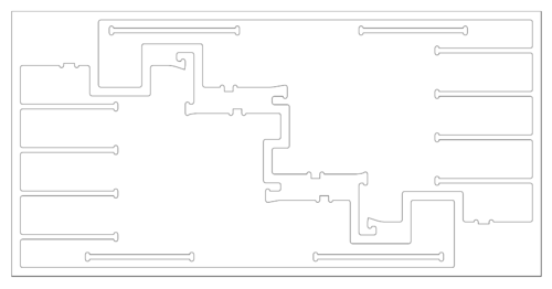
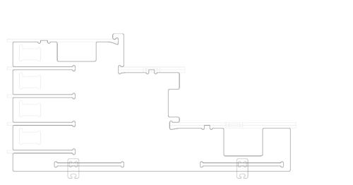
| + | Below is a sequence of images which shows an example of what kind of challenges we face while actually fabricating our design. Therefor the fabricationprocess is an important element in shaping our structural elements. | ||
| + | <br> | ||
| + | <br> | ||
| + | In the complete design, we have thought about drillhead sizes, woodplate thinckness, scalability, wood board sizes and the limits of the CNC milling machine. By making samples of just the connections on 1:10 and 1:1 scale, we have already found out some fabrication tolerances and we will keep working this way between the design and fabrication to create an actual fabricated 1:1 model as an end goal for this MSc1 course. | ||
| + | |||
| + | [[File:111130 cutout parts animation 001.png|500px|thumb|left|01 first design sketch without keeping wood board mapping in mind]] | ||
| + | |||
| + | [[File:111130 cutout parts animation 002.png|500px|thumb|left|02 design without legs and horizontal elements]] | ||
| + | |||
| + | [[File:111130 cutout parts animation 004.png|500px|thumb|left|03 placing of two identical parts on 2440x1220mm wood board]] | ||
| + | |||
| + | [[File:111130 cutout parts animation 003.png|500px|thumb|left|04 adjustment for central overlapping area]] | ||
| + | |||
| + | [[File:111130 cutout parts animation 006.png|500px|thumb|left|05 still two critical overlapping areas]] | ||
| + | |||
| + | [[File:111130 cutout parts animation 005.png|500px|thumb|left|06 adjusted design pieces on wood board ready for CNC milling]] | ||
| + | |||
| + | [[File:111130 cutout parts animation 007.png|500px|thumb|left|07 final adjusted design due to mapping on wood board]] | ||
| + | |||
</div> | </div> | ||
Revision as of 08:39, 1 December 2011
Team
And us:
Please use our feedback form and help us improve.
Public progress document
Follow us on Twitter: @HyberPublicNL
Our website (under construction) : www.HyperPublic.nl
HyperPublic : Theory: Home / Project B: Home
Development path
01 - testing fabrication methods
02 - presenting design ideas and incorporating feedback in design
03 - generate an overview of available materials and making design scalable
04 - testing tolerances and usability scale 1:10 with CNC milling machine (in absence of lasercutter)
05 - generating final 1:10 scale model to present to protoSPACE staff incuding Kas Oosterhuis weeks before final presentation
06 - using feedback to adjust and generate a part of the design scale 1:1 to face final challenges in connections, size and weight
07 - after a 'go' talk to large scale manufacturers in the area to help them sponsor machine time on large scale CNC milling machines
08 - gaining approval by presenting to protoSPACE staff to create the complete project scale 1:1 and showing final calculations
09 - build final design scale 1:1 with sponsoring of milling time by company and only material investment of Hyperbody
10 - taking surveys to compare to survey at the beginning of the semester to see if our goals are met
11 - structure all relevant generated texts, (computer)models and knowledge in a form future users could learn from or can adjust (parts of) the design
Fabrication
Below is a sequence of images which shows an example of what kind of challenges we face while actually fabricating our design. Therefor the fabricationprocess is an important element in shaping our structural elements.
In the complete design, we have thought about drillhead sizes, woodplate thinckness, scalability, wood board sizes and the limits of the CNC milling machine. By making samples of just the connections on 1:10 and 1:1 scale, we have already found out some fabrication tolerances and we will keep working this way between the design and fabrication to create an actual fabricated 1:1 model as an end goal for this MSc1 course.
HyperPublic : Project B: Home
